AUTOParkit System performance is based on Machine Cycle Times. All movements are recorded (timestamped) by the AUTOParkit System. Within the AUTOParkit System Machine Cycle Time, exist 3 primary cycle times: Load Bay, Lift, and Shuttle that are integrated.
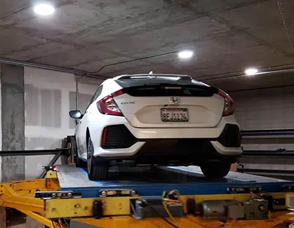
Car in the Load Bay

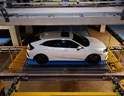
Car on a Lift
Car on a Shuttle
One of these cycle times will dominate or govern the Machine Cycle Time. Our process for properly matching sufficient equipment to meet the Peak-Hour-Demand (Peak-Hour-Demand is derived from the traffic study) for a project is what sets us apart. We do not build a system hoping the Machine Cycle Time will meet the system throughput, it is designed to meet or exceed Peak-Hour-Demand. We calculate the Machine Cycle Time or simulate the system so we can adjust the amount of equipment necessary for the required performance.
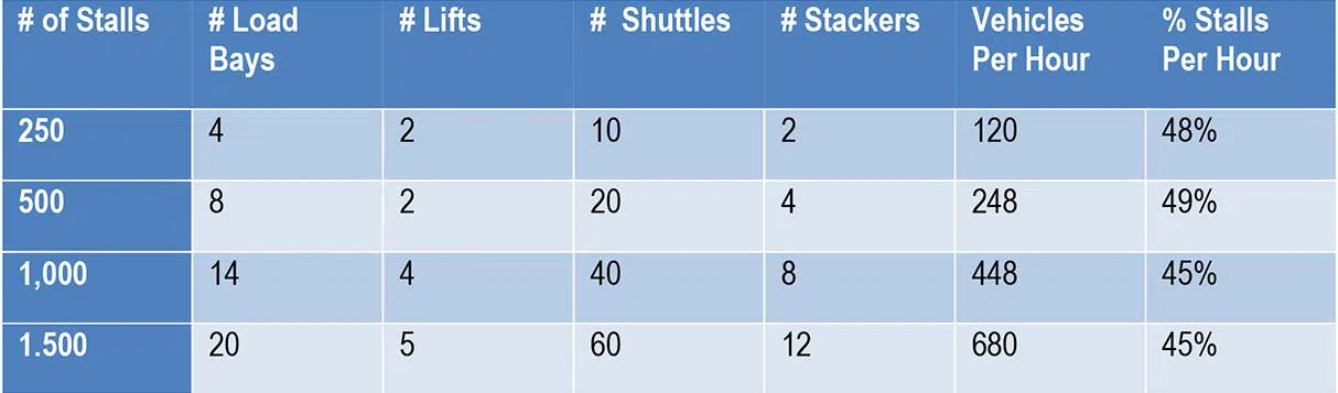
Below is a table with some examples of various sizes of fully automated garages with their associated equipment and automated system throughput. Please note: These are not maximum throughput, but rather designed to meet a site’s Peak-Hour-Demand.
Impacts on performance
AUTOParkit was conceived with a modular/scalable architecture that allows for every subsystem to run independently of all other subsystems. Parking and retrieving of vehicles is NOT done in a linear fashion, but with simultaneous movement of multiple vehicles.
Ratios: We evaluate equipment ratios such as number of Load Bays/Lift, number of Shuttles/Lift, and number of Stackers/Load Bay to determine the dominant cycle.
Travel distances: The distance of vehicle travel, both vertical and horizontal movement is critical for impacting performance. Ideally, Lifts are in the middle of the Rack Structure so that the horizontal distance is cut in half. Likewise, if the Load Bays level can be in the middle it reduces the vertical distance in half.
Lifts Located Outside of Load Bays: Another critical design decision is to locate the Lifts outside the Load Bays. When a Lift is outside of the Load Bay it allows for independent vertical movement.
Rotating Vehicles: Rotating a vehicle so a user pulls forward when exiting an AUTOParkit Load Bay is essential for safety, convenience, and system performance. Vehicle rotation is normally completed during the park transactions to help reduce the retrieval transaction. Please note that orientation of Load Bays may NOT require rotation of vehicles which would increase system throughput. This design is possible if the site has street access from both sides of the garage. Our design team would consider positioning the entry load bays on one side and the exit bays on the opposite street side. This layout delivers several benefits. 1) One way entry/exit delivers improve the vehicular flow. 2) No need to add rotation platforms.
Use of Stackers for “Burst Mode”: Stacker is a subsystem that stacks pallets. A single Pallet can be loaded or unloaded from a Stacker. The Stacker is also capable of loading and unloading a bundle of pallets. “Burst Mode”, used during Peak-Hours to reduce the cycle time of a Load Bay, is the coordination of the Stacker and Load Bay for the exchange of a single pallet. A Load Bay simultaneously can deliver a car for parking to a Lift and utilize an empty pallet from the Stacker so it’s ready to accept another vehicle. Conversely, the Load Bay can simultaneously unload an empty pallet to the Stacker and receive a vehicle from the Lift.
Case EVALUTIONS
The types of case scenarios that can be evaluated during the cycle-time-analysis vary depending on the project use: office, multi-family, mixed-use, event/entertainment, medical, etc. Below is a sample of case scenarios.
Parks Only Per Hour
Retrieves Only Per Hour
Park/Retrieve Same Level
Park/Retrieve Different Level
Retrieve Worst Case
Etc.
Speed kills: This was always a motto used when testing an automated system and defining machine cycle times. It was based on the theory of finding the slowest operation which could be anywhere from an operator [human], to physics [mechanical], or chemistry, even intra-communications or computational, and then finding a way to improve the performance of that step which would ultimately improve the overall cycle time.
So, what makes a fully Automated Parking System slow?
There can be several competing factors but one that stands out is a single transaction methodology.
When an ASRS (AUTOMATED STORAGE & RETRIEVAL SYSTEM) is only moving one thing (in this case a vehicle) at a time, the cycle time is inherently limited by the speed of a single transaction. The AUTOParkit System moves multiple vehicles simultaneously which dramatically improves throughput. This allows the AUTOParkit System to retrieve a vehicle in 40-180 seconds.
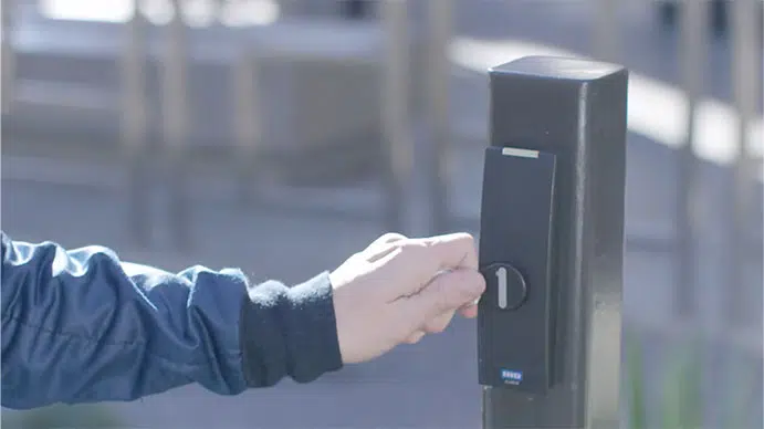
An innovative feature of the installation at the Helms Bakery District is the use of strategically placed campus-wide Remote Retrieve Kiosks (RRK). The RRK allows a driver to request their vehicle while they are walking to the fully automated parking system. “A user can actually experience what is called zero-wait-time”, We start every design to meet Peak-Hour-Demand, so by taking advantage of the RRK and the dwell time of a driver walking to the parking garage we can actually have their vehicle ready upon arrival or zero-wait-time.”
Seconds count.
Another clever feature at the Helms Bakery District was the use of high-speed garage doors. A typical garage door opens in 8-10 seconds. The overhead doors at the Helms Bakery District are less than 3.
Performance Summary Case Study 771 Stalls
Equipment Summary
Load Bays 12
Lifts 3
Lift w/ Turntable 3
Shuffles 18
Shuttles 24
Stackers /Bundler 4
Stalls 771
Equipment Summary
Load Bay to Lifts 4:1
Lift to Shuttles 1:10
Equipment Summary
Load Bay to Lifts
Lift to Shuttles
Shuttle Cycle
Equipment Summary
Load Bay Level to Level 2A 17’-0”
Load Bay Level to Level 2B 26’-4”
Load Bay Level to Level 2C 35’-6”
Analysis Notes:
317.83 Vehicles per hour or 41.22% of the total number of stalls.
The system is governed by the Lift Cycle time and the lift’s distance of travel. Two different transfer characteristics were accounted for in the analysis.
The analysis calculates system performance based on design constraints over a one-hour period with all resources available and executing concurrently.
AUTOParkit CYCLE TIME ANALYSIS - 711 STALLS
| TITLE HERE | TOTALS |
|---|---|
| CASE 1 Vehicles Per Hour Per System Different Level 100% Rotate | 317.83 |
| CASE 2 Vehicles Per Hour Per System Different Level 100% Rotate | 240.44 |
| CASE 3 Vehicles Per Hour Per System Different Level 50% Rotate | 337.00 |
| CASE 4 Vehicles Per Hour Per System Different Level 0% Rotate | 357.00 |
| CASE 5 Vehicles Per Hour Per System Same Level 100% Rotate | 357.00 |
| CASE 6 Vehicles Per Hour Per System Same Level 50% Rotate | 395.00 |
| CASE 6 Vehicles Per Hour Per System Same Level 0% Rotate | 435.00 |